Pressure Vessel Thickness Calculation
Design Formulas
Minimum thickness requirement (UG-16)
The minimum thickness requirement of any pressure retaining component (excluding corrosion allowance) is 1.5 mm in accordance with the provisions of UG-16 i.e.
Thickness, MAWP and Volume of Cylindrical Shells

Thickness
The thickness required (\(t_c\)) to handle circumferential stress arising due to internal pressure (\(P_i\)) is given as:
If \(P_i \leq 0.385SE\), using UG-27(1)
else if \(P_i > 0.385SE\), using Appendix 1-2(1)
The thickness required (\(t_l\)) to handle longitudinal stress arising due to internal pressure (\(P_i\)) is given as:
If \(P_i \leq 1.25SE\), using UG-27(2)
else if \(P_i > 1.25SE\), using Appendix 1-2(3)
where,
The shell thickness excluding corrosion allowance (\(t\)) is the highest of the thickness amongst \(t_c\), \(t_l\), \(t_u\):
MAWP
The MAWP for the available thickness is determined for circumferential stress (\(MAWP_c\)) as:
If \(t \leq \frac{R}{2}\), using UG-27(1)
else if \(t > \frac{R}{2}\), using Appendix 1-2(2)
The MAWP for the available thickness is determined for longitudinal stress (\(MAWP_l\)) as:
If \(t \leq \frac{R}{2}\), using UG-27(2)
else if \(t > \frac{R}{2}\), using Appendix 1-2(4)
where,
The shell MAWP (\(MAWP\)) is the lowest of the MAWP amongst \(MAWP_c\) and \(MAWP_l\):
Volume
The inner volume (\(V\)) of a cylindrical shell is obtained from the following:
The volume of steel (\(V_m\)) for weight computation is obtained from the following:
Thickness, MAWP and Volume of Spherical Shells

Thickness
If \(P_i \leq 0.665SE\), using UG-27(3)
else if \(P_i > 0.665SE\), using Appendix 1-3(1)
MAWP
If \(t \leq 0.356R\), using UG-27(3)
else if \(t > 0.356R\), using Appendix 1-3(2)
Volume
The inner volume (\(V\)) of a spherical shell is obtained from the following:
The volume of steel (\(V_m\)) for weight computation is obtained from the following:
Thickness, MAWP and Volume of Ellipsoidal Head
For an ellipsoidal head the aspect ratio (\(\beta\)) is defined as:
where:
\(h\) is the inner height of the head
\(D\) is the inner diameter of the head skirt
this can be used to determine the inner height (\(h\)) of the ellipsoid when the aspect ratio (\(\beta\)) is known:
Factor (K) for ellipsoid is obtained as:
Thickness
Using the equation Appendix 1-4(1), the thickness for ellipsoidal head is given as:
MAWP
Using the equation Appendix 1-4(1), the MAWP for ellipsoidal head is given as:
Volume
The inner volume (\(V\)) of an ellipsoidal head is obtained from the following:
The volume of steel (\(V_m\)) for weight computation is obtained from the following:
where :
\(R=\frac{D}{2}\)
\(R_o=R+t\)
\(h_o=h+t\)
Thickness, MAWP and Volume of Torispherical Head
The following relationships are applicable:
Outer Diameter \(D_o=D+2t\)
Outer Crown Radius \(L_o=L+t\)
Outer knuckle radius \(r_o=r+t\)
Factor M for the torispherical head is obtained as:
where :
\(L\) is the inner crown radius as shown in figure above
\(r\) is the knuckle radius as shown in figure above
Thickness
Using the equation Appendix 1-4(3), the thickness for torispherical head is given as:
MAWP
Using the equation Appendix 1-4(3), the MAWP for torispherical head is given as:
Volume
The inner volume of the torispherical head is given by:
where :
\(c = \frac{D}{2} - r\)
\(h = L - \sqrt{(r + c - L)(r - c - L)}\)
The volume of steel (\(V_m\)) for weight computation is obtained by the subtracting the inner volume of the toridome from the outer volume of the toridome:
Thickness, MAWP and Volume of Hemispherical Head
The following relationships are applicable:
Inner Radius \(R=\frac{D}{2}\)
Outer Radius \(R_o=R+t\)
Thickness
If \(P_i \leq 0.665SE\), using UG-27(3)
else if \(P_i > 0.665SE\), using Appendix 1-3(1)
MAWP
If \(t \leq 0.356R\), using UG-27(3)
else if \(t > 0.356R\), using Appendix 1-3(2)
Volume
The inner volume (\(V\)) of a hemispherical shell is obtained from the following:
The volume of steel (\(V_m\)) for weight computation is obtained from the following:
Thickness, MAWP and Volume of Conical Head
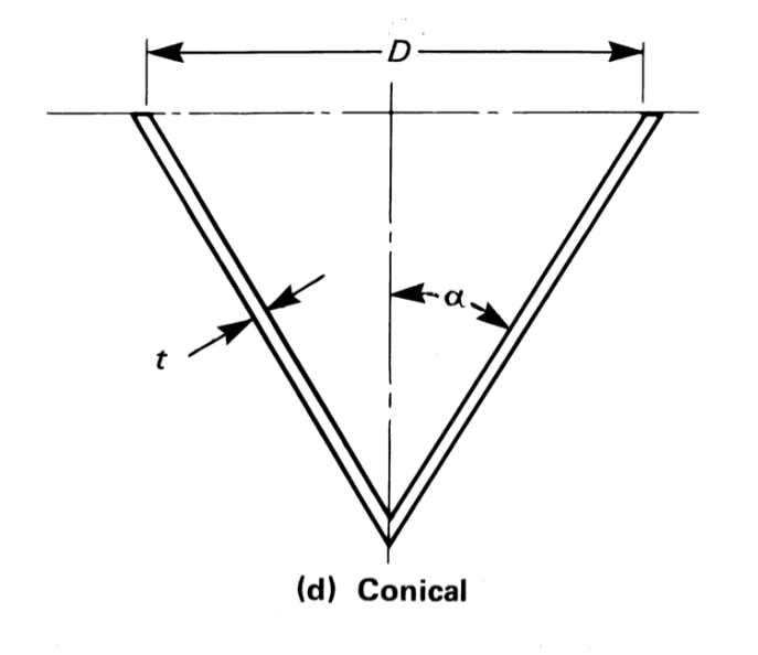
The following relationships are applicable:
Inner radius \(R=\frac{D}{2}\)
Outer radius \(R_o=\frac{D + 2t}{2}\)
Inner height \(h = \frac{D}{2 tan\alpha}\)
Outer height \(h_o = h + t\)
Thickness
For semi apex angle, \(\alpha\) not exceeding 30 degrees, the thickness and MAWP are obtained using the following formulas.
The thickness for conical head is obtained as :
MAWP
The MAWP for conical head is obtained as :
Volume
The inner volume (\(V\)) of a conical head is obtained from the following:
The volume of steel (\(V_m\)) for weight computation is obtained from the following:
Thickness, MAWP and Volume of Toriconical Head
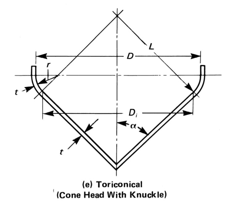
The following relationships are applicable:
the inside diameter of the conical portion \(D_i = D - 2r(1- cos \alpha)\)
the inner crown radius \(L = \frac{D_i}{2cos \alpha}\)
Thickness
The thickness of the knuckle portion (\(t_{knuckle}\)) can be obtained using Appendix 1-4(3) as given in (18) above.
The thickness of the conical portion (\(t_{cone}\))can be obtained using Appendix 1-4(5) as given in (20).
The thickness of the toricone is obtained as:
MAWP
The MAWP of the knuckle portion (\(MAWP_{knuckle}\)) can be obtained using Appendix 1-4(3) as given in (19) above.
The MAWP of the conical portion (\(MAWP_{cone}\)) can be obtained using Appendix 1-4(5) as given in (21) above.
The MAWP of the toricone is obtained as the minimum of the two.
Volume
Presently the program estimates the volume of the toricone, with a cone so the equations given in conical head sections apply. In future this may change by making use of more accurate relationships.
Calculation Procedure
Shell Evaluation
Step -1 : : Determine the unknown dimensions of the vessel shell from the dimensions as provided.
If the user has provided outer diameter (\(D_o\)) of the vessel then the inner diameter (\(D\)) can be obtained as :
If the user has provided inner diameter (\(D\)) of the vessel then the outer diameter (\(D_o\)) can be obtained as :
The inner (\(R\)) and outer (\(R_o\)) radius of the shell can be determined as:
Step -2 : Establish the dimensions under corroded conditions. The dimensions as used in the formulas shall be considered after considering the removal of material on account of corrosion. This implies adding the specified corrosion allowance on the inner dimensions which are exposed to the fluid and deducting the corrosion allowance from the nominal thickness provided. Thus,
Step -3 : Based on the value of internal design temperature lookup and interpolate the allowable stress of the specified material as furnished in ASME-II Part D.
Step -4 : Establish the minimum thickness of any component required to meet the requirement of UG-16 as below.
Step -5 : Calculate the thickness of the shell based on the internal design pressure i.e. \(t_c\) and \(t_l\) for cylinder and \(t_{sph}\) for sphere.
For cylindrical shell the thickness (\(t\)) shall be the maximum amongst \(t_c\), \(t_l\) and \(t_u\) i.e.
For spherical shell the thickness (\(t\)) shall be the maximum amongst \(t_{sph}\) and \(t_u\) i.e.
Step -5 : Calculate the required thickness of the shell (\(t_r\)) of the vessel shell after adding the corrosion allowance i.e. :
The provided shell thickness (\(t_n\)) is adequate if the provided nominal thickness exceeds the required thickness (\(t_r\)):
Step -6 : Calculate the MAWP of the shell using the design formulas as applicabe for the shell Shape (cylindrical or spherical) with the inner shell dimensions under corroded conditions. The thickness available (\(t_{cor}\)) under corroded conditions shall be used for the purpose of MAWP calculation.
Head Evaluation
Step -7 : : Determine the dimensions of the head.
It is assumed that the inner dimension of the head skirt is the same as the inner dimension of the cylindrical shell. Thus, \(D_1 = D_2 = D\) and \(R_1 = R_2 = \frac{D}{2}\).
The outer diameters of the head are obtained as:
The outer radiuses of the head are obtained as:
Step -8 : Determine the dimensions of the head in corroded conditions.
The relationship for head 2 are identical to the above.
Step -9 : Calculate the thickness of Head 1 (\(t_{h1}\)) and Head 2 ( \(t_{h2}\)) for the internal design pressure based on the relevant formula as applicable to the head shape. The calculated thickness of the head shall be obtained by application of the provisions of UG-16 for minimum thickness i.e.
Step -10 : The required thickness of the heads (\(t_{r1}\) and \(t_{r2}\)) is obtained by adding the corrosion allowance to the calculated thickness.
The provided head thickness (\(t_{n1}\) / \(t_{n2}\) ) is adequate if it exceeds the required thickness (\(t_{r1}\)/\(t_{r2}\)):
Step -11 : Calculate the MAWP of Head-1 (\(MAWP_1\)) and Head-2 (\(MAWP_2\)) using the design formulas as applicabe for the head shape (ellipsoidal, torispherical, hemispherical, conical or toriconical) with head inner dimensions under corroded conditions. The thickness available (\(t_{cor1}\)/\(t_{cor2}\)) under corroded conditions shall be used for the purpose of MAWP calculation.
Overall MAWP and Hydrotest Pressure
Step -12 : Determine the overall MAWP of the vessel which is the least amongst the MAWP as determined for the shell and the heads.
Step -13 : Determine the hydrotest pressure requirements as per the provisions of UG-99 (b).
where :
\(S_t\) is the allowable stress of the material at hydrotest temperatures.
Volumes and Weights
Step -14 : : Determine the inner volume of the shell (\(V_{sh}\)), Head-1 (\(V_{1}\)) and Head-2 (\(V_{2}\)) using the formulas as applicable to the geometry.
The volume of the vessel (\(V\)) is obtained as:
Step -15 : : Determine the material volume (steel volume) of the shell (\(V_{msh}\)), Head-1 (\(V_{m1}\)) and Head-2 (\(V_{m2}\)) using the formulas as applicable to the geometry. Knowing the density of steel (\(\rho_{steel}\)) the fabricated weight of the shell(\(W_{sh}\)), Head-1 (\(W_{1}\)) and Head-2 (\(W_{w2}\)) can be obtained as:
The fabrication weight of the vessel is obtained as:
Knowing the markup weight as a percent (\(\zeta\)) for additional items like vessel supports, nozzles etc. the gross fabrication weight of the vessel is obtained as:
Knowing the density of water (\(\rho_{water}\)) the hydrotest weight of the vessel (\(W_t\)) is obtained as: